EV1077 Battery Cell Voltage Emulation Board
Simulating high-voltage batteries at cell level for system voltages of up to 1,000 V
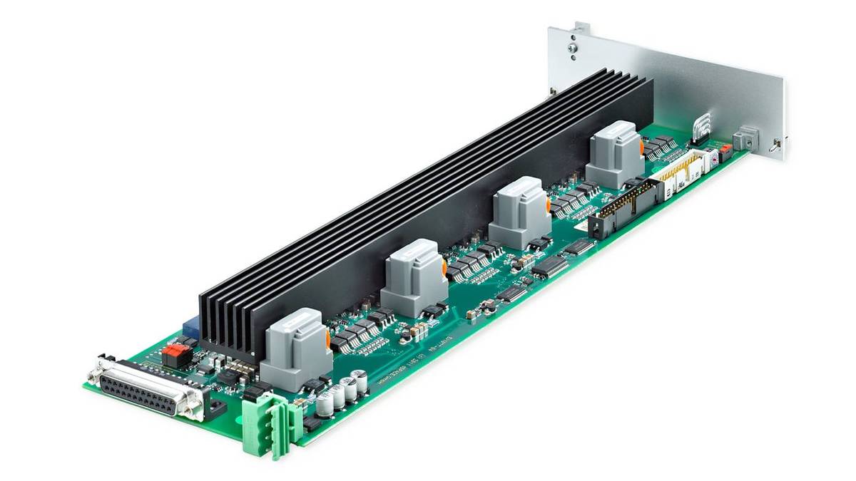
dSPACE provides the high-precision, four-channel EV1077 Battery Cell Voltage Emulation Board for the HIL test of battery management systems (BMS) on the voltage level. The board makes it possible to simulate high-voltage batteries at cell level.
- Simulation of high-voltage batteries at cell level with a total voltage of up to 1,000 V
- High-precision battery cell voltage emulation for use with a SCALEXIO system
- Integrated electrical failure simulation
Application Areas
Testing battery management systems (BMS) requires the precise emulation of the voltage level of each individual cell of a battery pack.
For testing the BMS used in e-mobility and stationary applications, the four-channel EV1077 Battery Cell Voltage Emulation Boards are installed in a SCALEXIO hardware-in-the-loop (HIL) system and controlled by a dynamic battery simulation running on the HIL system. These test systems are ideal for testing BMS with system voltages of up to 1,000 V.
Key Benefits
The EV1077 Battery Cell Voltage Emulation Board emulates a controllable, highly precise terminal voltage for single battery cells. Depending on the battery type and the test focus, several boards can be used in one HIL system. Due to its compact size, up to 32 cells can be combined in one 19'', 3-U module or up to 128 cells in a 19'', 12-U rack.
Cell Emulation Setup
Cell voltage emulation is performed with several EV1077 boards. The number of these controllable buffer amplifier boards is configured to match the battery type. The boards supply a continuously adjustable voltage, in the range 0 to 6 V. This relatively wide range means that damaged cells can be emulated. For example, a voltage higher than the nominal voltage simulates a cell's increased internal resistance during charging.
The voltage is output with a precision of ±0.5 mV across the entire working temperature range. The voltage is galvanically isolated, allowing the modules to be connected in series up to a maximum system voltage of 1,000 V.
The maximum current that can be supplied or sunk is 2 A, which enables testing of passive and active cell balancing strategies.
| Hardware structure |
|
| Output voltage |
|
| Resolution |
|
| Precision (across the working temperature range) |
|
| Working temperature (environment) |
|
| Maximum current (sink/source) |
|
| Isolation |
|
| Connection |
|
| Maximum update rate for all cells |
|
| Fault simulation |
|
- Battery Management Systems Developing and testing battery management systems for electric vehicles
- BMS Testing Solution dSPACE BMS testing provides best-in-class battery cell emulation and real-time-capable battery models for any use case.
- Shaping the Future of Battery Technology When it comes to Electro Mobility and Electric Vehicles, battery management systems (BMS) are safety-critical. Watch the recording of our Innovation Coffee Break demo (November 9, 2020) to learn how to test your BMS with dSPACE strength.
- Next Level BMS Testing Experience a first introduction and demonstration of the new dSPACE BMS Testing Solution.
Drive innovation forward. Always on the pulse of technology development.
Subscribe to our expert knowledge. Learn from our successful project examples. Keep up to date on simulation and validation. Subscribe to/manage dSPACE direct and aerospace & defense now.


