ZF Luftfahrttechnik (ZFL) and Sikorsky have teamed up to develop a new electrical rotor control system (LIBRAS™) that provides primary flight control and individual blade control for vibration and noise reduction, power savings, and additional performance enhancements for helicopters in a single system. A dSPACE system is being used to read and process sensor data from the rotor head and control the system to help identify and optimize control functions.
In 1939, the world got a glimpse of the first successful helicopter flight. The VS-300 was conceived by aviation pioneer Igor Sikorsky. It featured a single engine and a three-blade rotor designed with a variable pitch to capture the air flow and enable the helicopter to rise vertically into the air and fly. Since then, the basic configuration of the classical helicopter has not changed by much. Helicopters still rely upon bladed rotors to help them take off, land, hover, and fly forward and backward, and still have combustion engines for power. As helicopters became larger and heavier, hydraulic control systems were integrated to help pilots manage flight movements. But in this era of electrification, the helicopter is primed for significant transformation.
Shifting from Hydraulic to Electrical Solutions
While today’s helicopter control systems still use hydraulic servos to move the aerodynamic surfaces, the interest is shifting to electrical solutions. But before a fully electric helicopter can be achieved, proof is needed to show that hydraulic components can effectively be replaced by electrical systems. International helicopter components supplier ZF Luftfahrttechnik (ZFL) and aircraft manufacturer Sikorsky (a Lockheed Martin company) see the possibilities and are collaborating, along with support from the German and US governments, to develop a new rotor control technology based upon a purely electric blade control system for a high-speed rotor system. The eLectrIcal Blade Root Actuation System (LIBRAS™) would replace the hydraulic components that currently regulate flight control, and could bring forth numerous added benefits. “The new Individual Blade Control (IBC) system we are designing and testing in this program is an innovative way to control the helicopter and may offer many benefits by being able to individually control each rotor blade via its own electric actuator,” said Chris Sutton, Flight Sciences Technology Lead at Sikorsky. “Those benefits are things like reduced noise, better fuel efficiency, and vibration reduction in the cabin that would otherwise cause pilot fatigue, annoy passengers, and wear out components in the aircraft.”

Sikorsky S-92 rotor head with a traditional control system. Hydraulic servos (not visible) are located below the swashplate.
Controlling Blade Pitch – The Conventional Way
In a traditional helicopter design, the blade pitch of a rotor determines how the aircraft will lift and fly. Changes in airspeed and the rate of climb or descent are all regulated by the angle of the rotor blades. The greater the pitch, the greater the air flow. The blade pitch is mechanically controlled by a swashplate device connected to the helicopter’s flight control system. The flight control system sends inputs to hydraulic servos, which in turn command the swashplate to move and adjust the angle of the rotor blades via pushrods as they travel in a circular path around the rotor shaft. While the swashplate device allows the pilot to move the helicopter in any direction, its design has kinematic restrictions. Because the swashplate is installed in the non-rotating fixed frame, the blade pitch motion is limited to one cycle per rotor revolution, making it far from optimal. ZFL and Sikorsky are developing Individual Blade Control (IBC) technology as a means of achieving a more efficient and optimized rotor design. This technology uses blade-individual actuators, one dedicated to each blade, that allow for both higher-frequency (usually harmonic) pitch variations and the once-per-revolution primary control combined within a single system. “The IBC system, in combination with being able to provide different inputs to each blade, can also apply what we call ‘higher harmonic control,” Sutton explained. “Traditional control systems can only apply steady and once-per-revolution control inputs to the rotor head. This just means that each blade pitches up and down once each time it makes a revolution. With higher harmonic control, the blades can be pitched two or more times as they travel one revolution. This higher harmonic control and individual blade control are what make things like vibration reduction and better efficiency possible with IBC, if you know how to apply them.”
Individual Blade Control (IBC) Technology
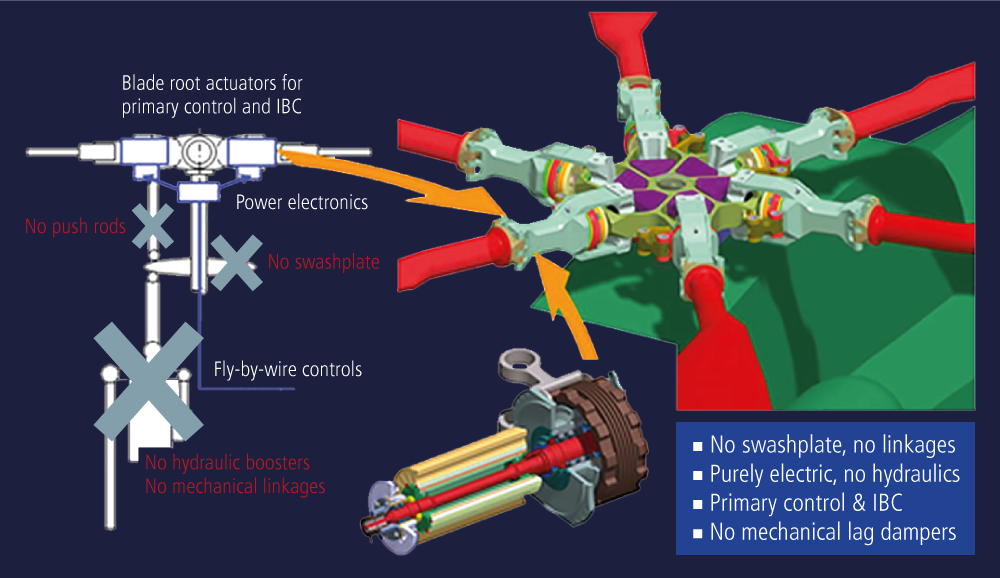
For many years, ZFL has pioneered the concept of IBC. In fact, several systems have been developed and successfully demonstrated during various wind tunnel and flight test campaigns. In flight tests using IBC technology, fuselage vibrations have been reduced by up to 90%, the radiated noise has been attenuated by 3 to 9 dB, and the rotor power requirement was consistently reduced by more than 5%. Moreover, such active systems enable in-flight rotor track and balancing to compensate for blade-to-blade dissimilarity and inherently provide reconfiguration capabilities to potentially compensate for dangerous foreign object damage (FOD) effects. ZFL has started to develop novel rotor control systems, which are based on multiple redundant electromechanical high-performance actuators. In the architectural design of this system, not only are all hydraulic elements replaced (no push rods, no swashplate, no hydraulic boosters), but all mechanical control linkages, from the fuselage to the rotor blades, are eliminated as well. With the swashplate removed, an IBC system can achieve full functionality, and the aforementioned benefits (vibration and noise reduction, power savings, and performance enhancements) can be achieved. Moreover, when the complete hydraulic system is removed, there is an added safety benefit – the hot, pressurized, and flammable oil required for hydraulics to function no longer has to be onboard the aircraft.
Matching the Power of Hydraulic Actuators
While IBC technology and its electrical counterparts can offer many benefits, more work has to be done to match the very high power densities of hydraulic actuators. To achieve a competitive system weight, a completely new control system topology must be leveraged. Specifically, the primary control and the IBC functionalities have to be combined into a single system. This kind of design could provide the same level of reliability required for the primary control system, enabling use for safety-critical active control applications, such as ground resonance suppression. Moreover, it is conceivable that local failures from a single blade (be it the blade pitch actuator or the blade itself) could be compensated for through suitable reconfiguration of the control inputs applied to the remaining blades. Sutton noted that respective simulations have supported this concept, but it has yet to be tested with hardware in a relevant environment.
Validating the Concept
To validate the feasibility of the IBC design concept, Sikorsky and ZFL have partnered to set up a technology demonstration that tests full-scale hardware under realistic operating conditions. Sikorsky has defined all relevant high-level system requirements for the mechanical and primary control performance, operating loads, electrical interfaces, and IBC performance. Simulations have been conducted to estimate the required IBC authority at the respective higher harmonic frequencies. Expectations are that IBC technology will not only be suitable for established applications like vibration and noise reduction, but also for different and innovative capabilities that relate to the unique characteristics of the co-axial rigid rotor (optimizing lift offset and/or enabling smaller inter-rotor spacing).
System Architecture
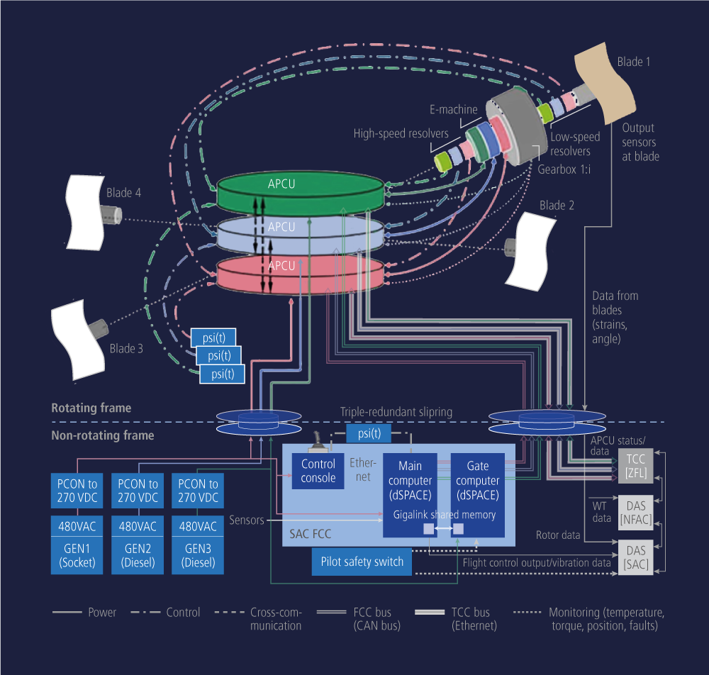
On the basis of the identified system requirements, ZFL has synthesized a system concept and harmonized it with Sikorsky. The high-level system architecture features a LIBRAS™ rotor hub, containing the electromechanical actuators (EMAs) along with the power and control electronics, called the Actuator Power Control Unit (APCU). Most of the ZFL components reside in the rotating frame and are shown in red, green, and blue color in the system architecture diagram. The hardware and software elements for the control and supply functions are primarily located in the non-rotating frame (blue). The overarching triple-redundant architecture is easily recognized (shown in red, blue, and green, one color for each ‘lane’ of the triple-redundant system) and carried through from the power supply to the electromechanical actuator and its sensors. The main components of the system architecture are summarized below:
Rotating frame components:
- 4x electromechanical actuator (EMA)
- 3x Actuator Power Control Unit (APCU) (to process the incoming command signals, to control the power electronics, to provide position control for the actuators, and to monitor compliance with the various limits [currents, torques, temperatures, etc.])
- 3x rotor azimuth sensors (required to provide a reliable reference of the actual rotor position)
- Data acquisition systems (DAS) to receive sensor signals and monitor blade loads and other safety-relevant flight parameter
Non-rotating frame components:
- 1x flight control computer (FCC) consisting of: Pilot Control Console (provides primary control operator input) Higher Harmonic Controller (a dSPACE system synthesizes suitable amplitude and phase values for the higher-harmonic and/or blade-individual components based on entered presets or computed from real-time sensor signals)
- Gate Verification System (a separate dSPACE system that monitors pilot and HHC control inputs against a control range and control rate envelope to inhibit commands which are invalid and/or out of range)
- 1x test control computer (TCC)
- 3x power supply
- Data acquisition systems
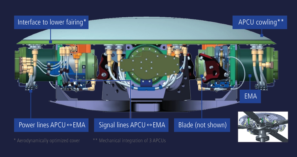
Sikorsky and ZFL have built their test platform, which includes an advanced control system. For this test platform, the rotor hub and rotor blade design have been completed and manufactured, along with actuators, power electronics, and power converters. The rotor hub and rotor blades have been integrated with other system components, resulting in a very sophisticated design of both mechanical and electronic parts. Figure 5 shows the custom power and control electronics hardware (APCU) installed into a rotor fairing for cooling and low drag, as well as the custom, highly integrated, highly reliable, and high power density rotor actuator (EMA).
Simulation and Testing
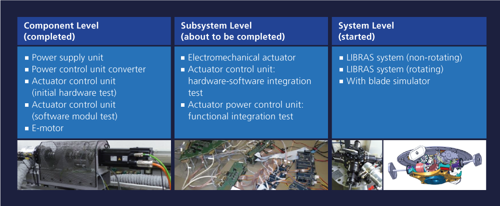
To verify the mechanical design and performance of the electromechanical actuators and software functionalities, Sikorsky and ZFL are conducting simulations and tests at the component level, the subsystem level, and the system level. Various software tests are also being run within a highly automated test environment to verify requirements based on the DO-178 standard. This includes such things as complex sensor data processing, position control, cross-communication, voting, and error handling functionalities of the actuator control unit software. Additionally, thermal simulations were conducted to validate heat distribution under various operational conditions.

Assembly of the power electronics on the aluminum cowling (left) and the electromechanical actuator (right).
dSPACE System Features
ZFL and Sikorsky use dSPACE systems for a variety of applications in this research effort. For example, control and monitoring of all test rigs for component and subsystem testing at ZFL is performed by dSPACE systems. On the Sikorsky side, the dSPACE system features four DS1005 PPC Boards for processing and computing real-time applications, a DS2202 HIL I/O Board for simulating and measuring signals, a DS4002 Timing and Digital /IO Board for generating and capturing digital signals, and a DS2302 Direct Digital Synthesis Board for simulating complex sensor signal waveforms. The dSPACE controller receives sensor data inputs, such as accelerometers and strain gauges on the rotor, processes the data, and then utilizes this information in a control algorithm to identify optimized control inputs. The dSPACE system suggests amplitudes, higher-harmonic phases, and individual blade commands to reduce or change parameters of interest such as vibration, blade loads, or power required. The commands for the pilot controls, along with higher-harmonic and blade-individual controls, are then digitally packaged and sent as a triplex stream by the dSPACE computer to the ZFL IBC system at the rotor head. “The dSPACE system is central to the task of achieving targeted objectives,” said Sutton.
Outlook and Future Testing
Upon completing the majority of qualification testing at ZFL in Germany, a full system will be shipped to Sikorsky in the United States in 2020 to begin preparation for the System Integration Lab tests at Sikorsky. The major objectives of the tests are:
- Verify test article assembly and mechanical integration of the LIBRAS IBC system
- Verify Sikorsky Flight Control Computer operation (of which the dSPACE system is a main component) in the fully integrated system
- Validate LIBRAS system operation through a range of rotor speeds and control motions
- Demonstrate robustness of the triplex system architecture to induced faults
- Satisfy entrance criteria requirements for the wind tunnel facility (endurance testing, vibration testing, and overspeed testing)
After completion of these tests, wind tunnel testing will take place to demonstrate primary flight control, to quantify the benefits of IBC technology, and to evaluate the IBC design and its implementation challenges. During wind tunnel testing, the dSPACE system will package commands and send them, along with pilot controls, to a human pilot who will use a joystick to fly the model from a control room, adjacent to the wind tunnel. Once the commands are implemented, the controller will read the sensor data to measure what changed and then repeat the process. “In the wind tunnel, we will spend time at a variety of airspeeds and conditions to see how much ability the IBC system has in affecting parameters in a way that could benefit our future helicopter platforms,” Sutton said. “If the System Integration Lab and wind tunnel tests go very well, we will consider a follow-on effort involving a flight test in the future – this is the next logical step after a wind tunnel test in our technology development.” In the end, Sikorsky and ZFL hope to demonstrate the feasibility of a purely electrical, ’swashplateless’ control system that combines both primary and IBC functionalities.
Chris Sutton, Sikorsky
About the author:

Chris Sutton
Chris Sutton is the Flight Sciences Technology Lead for the Engineering Sciences group at Sikorsky, a Lockheed Martin Company in Stratford, Connecticut, USA.


