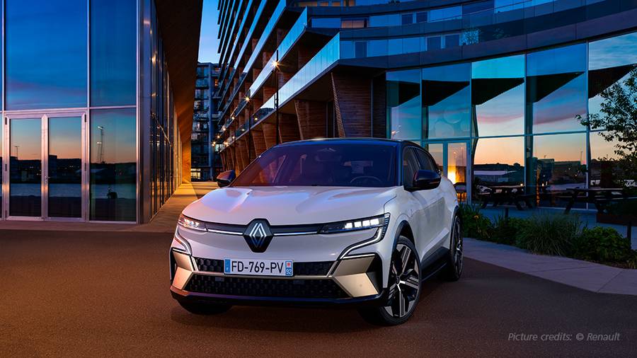
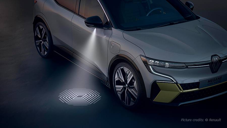
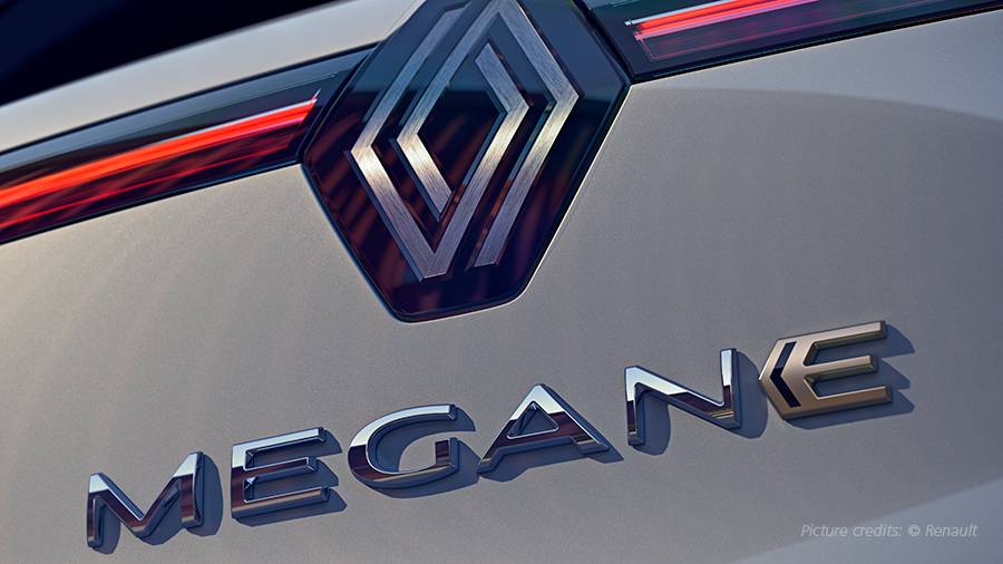
With the new Megane E-TECH Electric, French car manufacturer Renault presents the first of a new generation of electric vehicles. The compact class model, based on the newly developed CMF EV platform, combines all of Renault's expertise as a pioneer of affordable electric mobility that is suitable for everyday use. In order to meet these requirements in onboard charging technology as well, the company also relies on a highly efficient and compact topology for the power electronics. The development of the onboard charger, consisting of a Vienna rectifier and two DC/DC converters, was undertaken by Renault itself. To test the ECU at an early stage, Renault relies on dSPACE expertise.
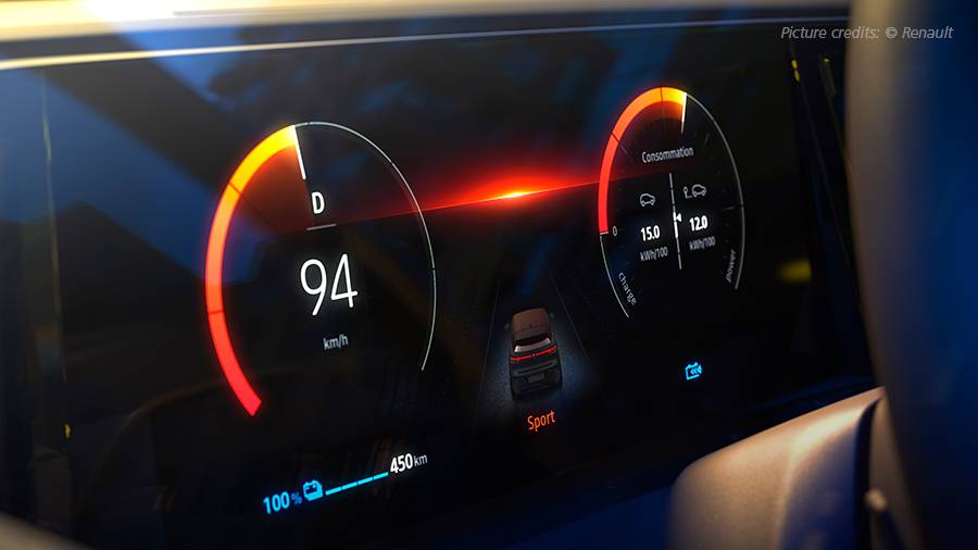
400,000 e-vehicles sold in Europe over the last ten years is the best proof of a company's electric expertise; with the Zoe in particular, Renault is the market leader in many countries. Up to 470 kilometers of range in the WLTP test cycle, the slimmest battery on the market at 11.0 centimeters high, and the largest info display area in a vehicle in the compact class are just some of the highlights with which the Megane E-TECH Electric redefines the boundaries for battery-electric vehicles. The electric model is available with two output levels with 96 kW/131 hp and 160 kW/218 hp. The battery is also available in two capacity levels: 40 kWh and 60 kWh. The batteries can be charged at various outputs and currents, including, depending on the version, at DC fast-charging stations with up to 130 kW. Thanks to a new-generation oil-cooled synchronous motor with a wound rotor, it was possible to dispense with magnets containing rare earth materials.
There is a long-standing relationship between Renault and dSPACE, dating back to the early 2000s when dSPACE equipment was mainly used for combustion engines, transmissions and vehicle dynamics control units. It was natural to rely on dSPACE for the new vehicle concepts as well.
Caused by the e-mobility, Renault has now adopted numerous dSPACE hardware solutions and also modeling solutions, including FPGA modeling for inverters. Besides the charging validation, it is also worth mentioning that Renault has HIL test benches for electric drive train and the battery management system that are specifically tailored to Renault's battery architecture.
Development of the Onboard Charger
Renault chose an efficient and modern solution for the architecture of its charging solution, on the one hand to provide flexibility for the end customer, but on the other hand to be able to comply with current national and international regulations regarding grid quality. For this purpose, the company also relies on new types of semiconductors that increase efficiency and reduce installation space through higher switching frequencies of up to 200 kHz.
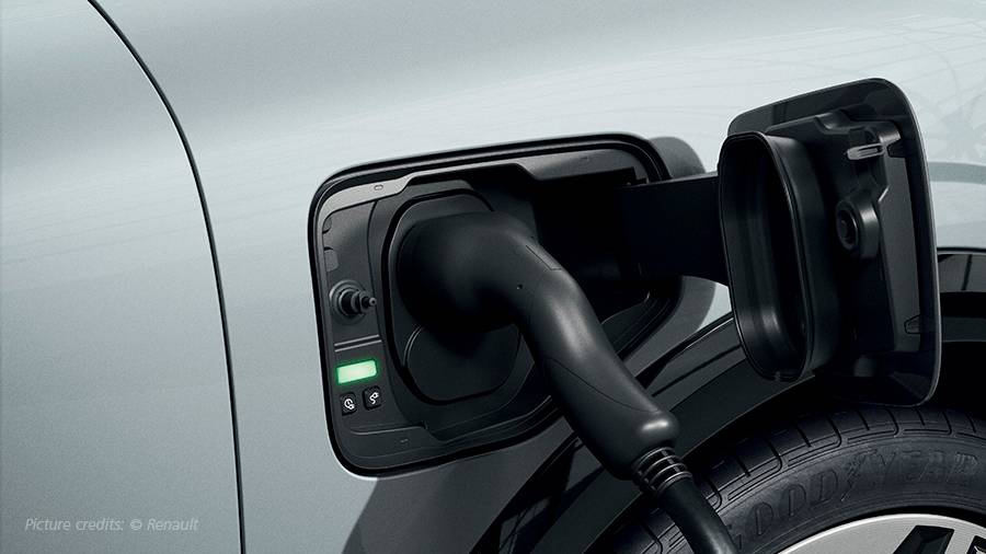
In addition to DC fast charging, in which the power electronics are installed in the charging station, AC charging uses a charger installed in the vehicle. The latter allows the battery to be charged at a conventional single-phase socket with 2.3 kW or at a three-phase wallbox with 22 kW.
Direct current, which must be converted from the mains alternating current, is required to charge the battery. The efficiency of the charging system plays an essential role here, which means that the choice of rectifier topology is particularly important.
For this purpose, Renault has opted for a two-stage design of the charging system. A Vienna rectifier is used for rectification and ensuring the requirements by the grid operator. This type of rectifier is a unidirectional, three-phase, active rectifier, which can achieve an efficiency of 99% or more. Unlike boost PWM rectifiers, the Vienna topology operates at three levels, which reduces inductance requirements and halves the voltage load on the switching devices. This in turn improves efficiency and power density.
Compared to traditional rectifiers, the Vienna rectifier has the following advantages:
- Better power factor correction (PFC) with better power quality according to EN 61000-3-2
- Reduced harmonic currents
- Current balancing between the phases and lower load on the power electronic components
Power Quality
In Europe, EN 61000-3-2 requires that power factor correction is incorporated into large consumer products. The EN 61000-3-2 standard refers to harmonic currents caused by electrical and electronic equipment whose input current is less than or equal to 16 A. In addition, the devices must be designed for connection to public low-voltage grids. The EN 61000-3-2 standard sets clear limits for harmonic currents. All electrical or electronic devices that fall under the EN 61000-3-2 standard are categorized into classes A to D.

Figure 1: Schematic diagram of the OBC system with input/output filter, Vienna rectifier, and DC/DC converter.
Validation Process and HIL Simulation
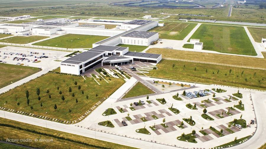
Renault has long used hardware-in-the-loop (HIL) simulation to validate ECU software, particularly in the powertrain area for gasoline, diesel, electric, and hybrid vehicles, but also for other ECUs. HIL validation has continued to expand, over the years, greatly complementing on-vehicle testing. In the powertrain sector alone, Renault currently operates 40 HIL test benches at its Titu Technical Center near Bucharest, Romania (figure 2). The Titu Technical Center is part of Renault Technologie Roumanie (RTR), a R&D center of the Renault Group.
The onboard charging system was developed entirely by Renault, both in terms of hardware and electronic control unit software. The validation process began at an early stage of development with a topology-oriented offline simulation based on model-in-the-loop (MIL) and software-in-the-loop (SIL). Before the real power electronics were available, the control board had already been put through its paces with a HIL test system.
Validation on an HIL test bench generally offers many advantages. It is less expensive than a prototype vehicle because the HIL test benches are generic and can be configured for most vehicle projects. Furthermore, the development time is shortened because the validation load can be distributed among several test benches and people. Another benefit of the HIL test bench is higher productivity, because software tests are possible even before the real components are available. In addition to the aspect of safety and flexibility compared to a real vehicle, HIL systems also score highly in terms of reproducibility and automated testing.
HIL simulation of power electronic circuits at the signal level offers advantages over tests on prototypes in terms of safety, among other things, since the high voltages and currents are only simulation variables. This also allows the targeted simulation of fault cases without the destruction of hardware prototypes.
Challenge: Highly Dynamic Power Electronics
HIL validation for the new onboard charging system presented Renault developers with unique challenges that differed significantly from those of most previous HIL applications.
In particular, the Vienna rectifier's switching frequency of 140 kHz and that of the DC/DC converter of 200 kHz place high demands on the HIL simulation, whose sampling and response times must be well below 1 µs. As a comparison: For combustion engines, the sampling time is usually 1 ms. The particular challenge is that the dynamic behavior of the very complex power electronic circuit must be calculated within the short sampling times.
With this in mind, it quickly became clear to the developers that simulation would not be feasible on the existing, processor-based SCALEXIO HIL test benches, due to the high switching frequencies. Therefore, the test benches were equipped with field programmable gate array (FPGA) boards from dSPACE, which are more suitable for such real-time applications.
Realization of a Highly Dynamic Validation System
The architecture of the HIL environment was modularized, i.e., the onboard charging system was divided into its functional groups. Individual models were created for the grid, the contactors and input filter, the Vienna rectifier, the two DC/DC converters and output filter, and the battery.
For the simulation of the grid, including the contactors and a complex filter network, the dSPACE Electrical Power Systems Simulation Package (EPSS) was used to implement a topology-oriented model. Due to the high switching frequencies of the power electronic circuits, speed-optimized FPGA implementations were necessary. The models for the Vienna rectifier and the DC/DC converters with output filter and battery were developed and implemented by dSPACE. All models are capable of accurately simulating the high dynamics required for the module and provide prepared interfaces for connecting the submodels.
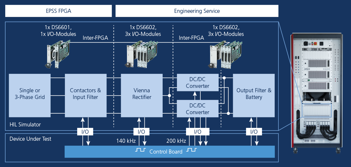
The modular structure of the individual topologies enabled a step-by-step and systematic commissioning. The models were implemented on three FPGA base boards. For low-latency exchange of signals such as DC link voltages and currents between the models, the FPGA boards were interconnected directly in the HIL simulator via fast inter-FPGA communication. The PWM and control feedback signals were, in turn, captured using FPGA multi-I/O modules connected directly to the FPGA base boards.
All modeling methods used so-called state space representations to describe the different switch state combinations. However, in order to achieve the best possible compromise between simulation accuracy and FPGA resource consumption, different types of switch models were used. The ideal and resistive switch models enable fast and very accurate models, but require high memory and resource consumption [EPE2021]. The models for the contactors, the input filter, and the DC/DC converters use these methods. An inductive/capacitive switch model enables the simulation of complex circuits with many semiconductor devices such as the Vienna rectifier in this application [PCIM2020].
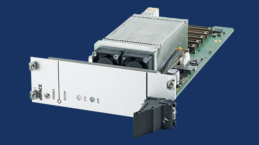
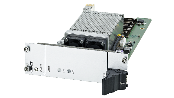
The DS6602 FPGA Base Board is equipped with one of the largest FPGA currently available in the Kintex® UltraScale™ family from Xilinx®. Its additional onboard RAM enables the storage of very large data sets, for example, model parameters, which are required for demanding simulations, especially in the field of electric drives. The DS6602 has four multi-gigabit transceivers (MGT) that enable very fast communication. In addition, multiple boards can be interconnected via the cable for internal FPGA communication to enable direct data exchange between FPGA stacks.
Validation Results
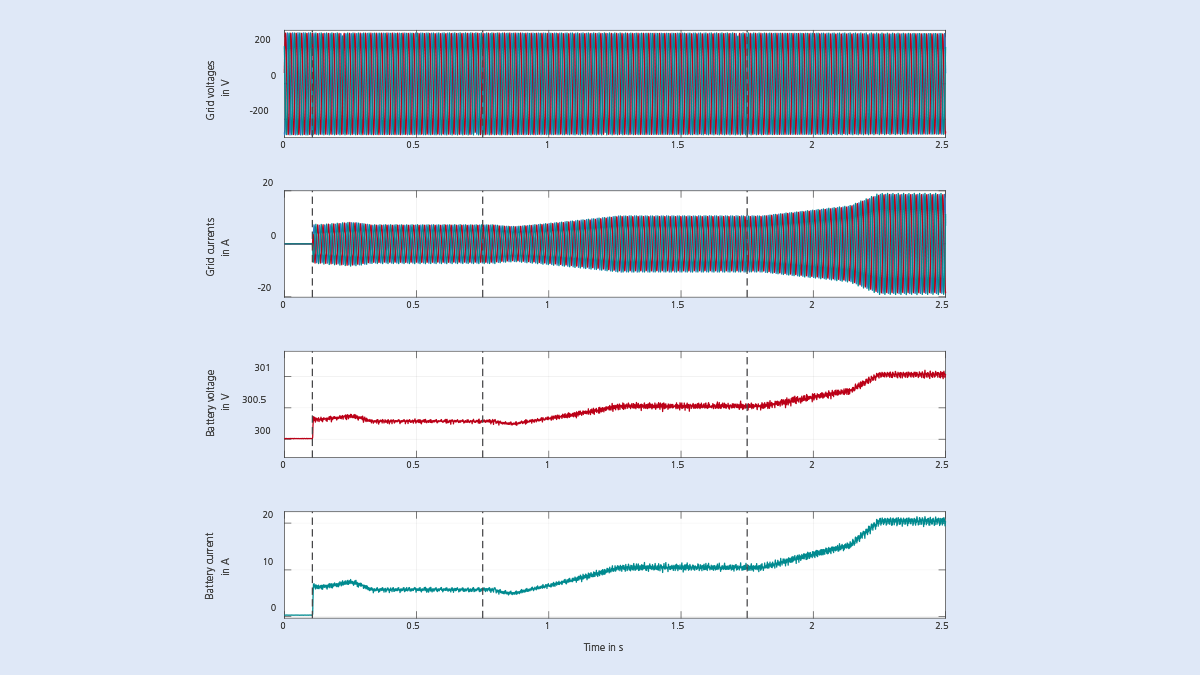
The measurement results from the closed-loop simulation of the onboard charging system are shown in figure 4. At t=0.1 s, the charging process is activated and a battery current of 5 A is requested. During a short startup sequence, first the control of the DC/DC converters is activated and afterwards the control of the Vienna rectifier. After this sequence, the requested current is fed into the battery. The controllers for the DC/DC converters ensure that the requested current is accurately set. At t=0.75 s and t=1.75 s, the charging current is further increased – from 5 A to 10 A, and then to 20 A.
The interconnections of the power electronic circuits are well considered in the multi-FPGA simulation of the onboard charging system. For example, by increasing the battery current, the charging power rises so that the supplying grid currents – simulated on a different FPGA – must increase accordingly. The controller of the Vienna rectifier adjusts these currents and ensures that they are in phase with the grid voltages.
Conclusion and Findings
When Renault decided to validate the control unit for the onboard charger, the developers were convinced by the benefits of the signal-level-based HIL simulation. As no prototype of the power electronics circuit is required and the high charging currents and voltages are only simulation variables, the tests can be conducted already in an early stage of the complete development process. With dSPACE’s expertise, comprehensive approaches, and simulation models for power electronics in combination with the latest FPGA platforms, Renault was able to successfully validate a newly developed onboard charging system, stable and reliable even at the high switching frequencies of the Vienna rectifier used.
Stefan-Valentin Popescu, Adrian Vlad, Renault
dSPACE MAGAZINE, PUBLISHED August 2022
About the authors

Stefan-Valentin Popescu
HIL Referent for Powertrain Software Validation department at Renault Technologie Roumanie in Titu Technical Center.

Adrian Vlad
HIL Pilot for Powertrain Software Validation department at Renault Technologie Roumanie in Titu Technical Center.

