Speed, safety, and comfort during a train journey – that should go without saying! ABB makes sure this is the case, using its high-performance traction converters for the main vehicle propulsion and auxiliary converters for onboard power supplies. To develop and test the control software for these converters in an effective and efficient manner, ABB relies on generic real-time simulation using dSPACE products.
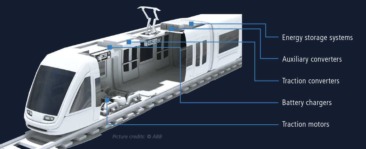
One of the most important parameters characterizing a modern rail vehicle is the tractive effort. While it is indeed the tractive force which sets a vehicle in motion, a high-performance traction chain also requires other sub-systems like auxiliary converters (Figure 1), which play an important role in the vehicle’s functioning. It is difficult to imagine a train ride today without the comfort of heating, ventilation and air conditioning, lighting, or outlets for charging portable devices. In addition, not only the passengers need a “cool” ride, but traction chain components such as traction converters, traction transformers, and traction motors also require cooling to ensure reliable and efficient operation. Furthermore, air compressors are essential for operating the braking system and the pantograph.
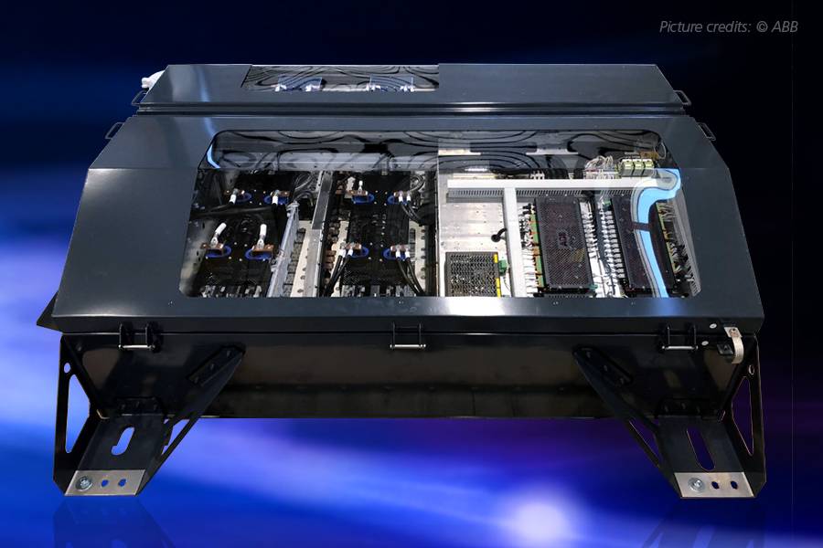
All these auxiliary loads in the train are powered by an auxiliary converter (AUX). ABB offers auxiliary converters for a wide range of vehicles, either integrated in the traction converter or as stand-alone units (Figure 2).
The Devil Is in the Detail
Hardware-in-the-loop (HIL) testing is the technical standard for testing the control software of traction and auxiliary converters. For this purpose, ABB uses the dSPACE Development Solution. For many years, ABB has benefited from dSPACE products – such as the HIL simulation of electric drives – to test and develop control software for optimal power transmission to the wheels. However, auxiliary converters have a higher switching frequency than traction systems. This in turn requires high simulation precision, and correspondingly high sample rates in the simulation environment – as only field-programmable-gate-array (FPGA)-based simulations can provide.
FPGA = Field Programmable Gate Array
FPGA stands for field-programmable gate array. FPGAs are used in digital technology to allow modifications in an integrated circuit’s functionality without replacing hardware. Instead, a specific integrated circuit is implemented as a particular configuration of the internal logic cells.
The main advantages of an FPGA are its flexibility and high speed for signal processing. In the EPSS case, the numerical solution of the discrete system equations for a power electronic circuit is computed on the FPGA.
Focusing on the Essentials
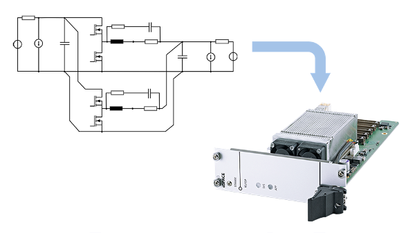
ABB needs a generic test environment to accommodate the wide variety of controllers and onboard systems in development and validation. This allows engineers to focus on their core tasks of developing and testing auxiliary converter software, and not have to deal with complex mathematical models or FPGA programming. Therefore, the dSPACE Development Solution had to be convenient, easy to use, and flexible to adjust parameters to different requirements. The solution, especially the Electrical Power Systems Simulation Package (EPSS), carries out rapid real-time calculations from a circuit diagram modeled with Simscape Electrical™ (Specialized Power Systems), e.g., using an FPGA. No specific expertise is required to use EPSS other than creating circuit topologies. No FPGA programming software has to be available, nor does the responsible engineer have to perform any time-consuming synthesis of the FPGA build themselves. Using the FPGA-based approach included in EPSS, fast computing steps in increments starting from a few hundred nanoseconds are possible – depending on the application – so ABB chose this package. The EPSS package thus allows the circuit diagram developed with Simscape Electrical™ to be transferred directly to the FPGA and executed in real time without any further implementation effort by the user. This saves time and money and conserves resources.
dSPACE Development Solution
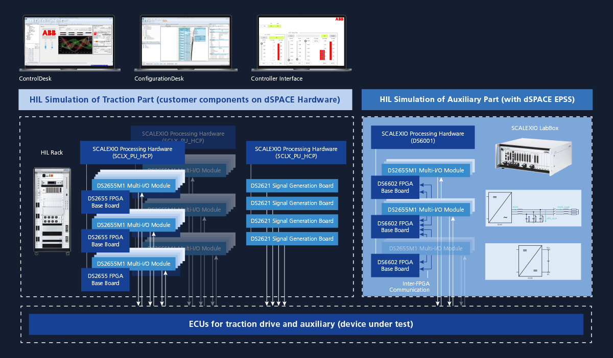
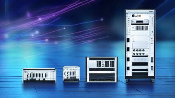
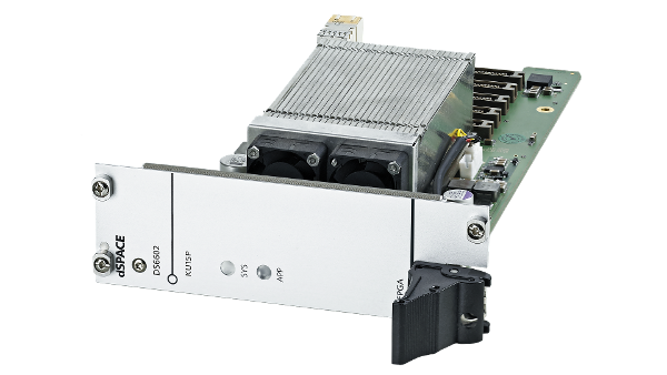
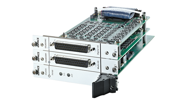
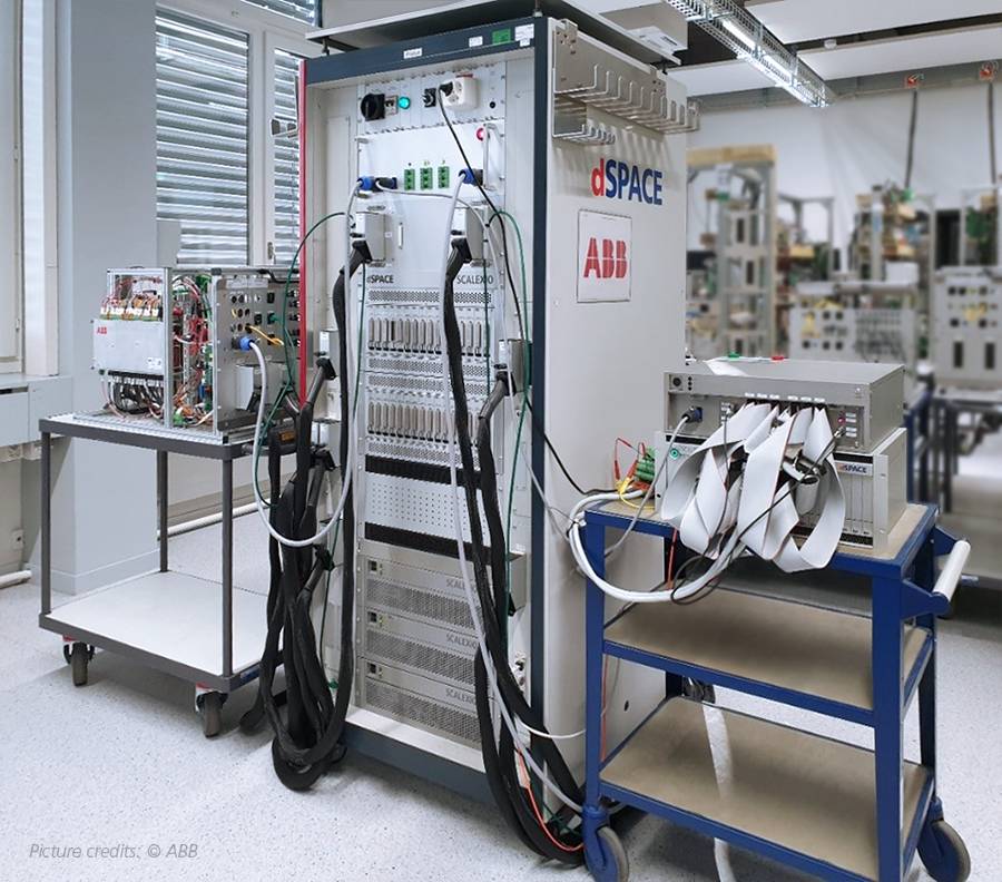
ABB uses SCALEXIO hardware together with the experiment and instrumentation software ControlDesk and the implementation software ConfigurationDesk. The dSPACE Electrical Power Systems Simulation Package (EPSS), which runs on a SCALEXIO unit with its dedicated processor, FPGA and multi-I/O boards (Figure 3) helps simulate the auxiliaries using FPGAs. When it comes to the simulation of auxiliary power converters, the resolution in step sizes of approximately 25 μs, which is usually used for traction simulation, is not sufficient. This is because the power semiconductors in auxiliary converters have higher switching frequencies (above 2 kHz), and the associated power electronics circuit components (inductors, capacitors, resistors, switches) have smaller time constants than in the traction system. The mathematical description of such systems requires deeper specialist knowledge in order to achieve an accurate real-time simulation (RTS).
Therefore, an approach was necessary that covered the following points:
- Physically correct modeling of the power converter by means of a circuit diagram
- Automatic generation of the mathematic description (differential equations) and discretization
- Simulation step size below 5 μs
- Exact consideration of the pulse-width modulation (PWM) switching signals
- Change of the parameterization, in particular of loads, during run time
- Precise recording of measurement data
All these points are intended to facilitate time-saving and reproducible testing of power converters.
Prior Analysis of the Models
As auxiliaries come in a variety of configurations and numbers (e.g., with or without a step-down DC/DC converter, more auxiliaries running in parallel), the question arises of whether the complex models can even be processed on a single FPGA, or if they must be split. If splitting is required, the point at which splitting can be performed must be identified so that the simulation remains stable and precise enough. The resulting units, which run on multiple FPGAs, must still be able to communicate with each other without problems using an inter-FPGA connection (Figure 5). EPSS offers extensive, user-friendly tools to identify the necessity of several FPGA boards and their configuration. In this manner, for example, a graphical user interface can display whether a circuit can be implemented on an FPGA, and which components or settings require a further FPGA board. If model splitting is unavoidable, easy-to-use model splitting blocks can be inserted into the simulation model. Various splitting processes are available. In a further graphical interface, users can analyze which splitting points and splitting methods lead to a still-stable simulation and which splitting points are most suited for the available model. The connection of several FPGA boards can be conveniently configured via ConfigurationDesk and an integrated EPSS-specific inter-FPGA interface.

Detailed Comparison of Results
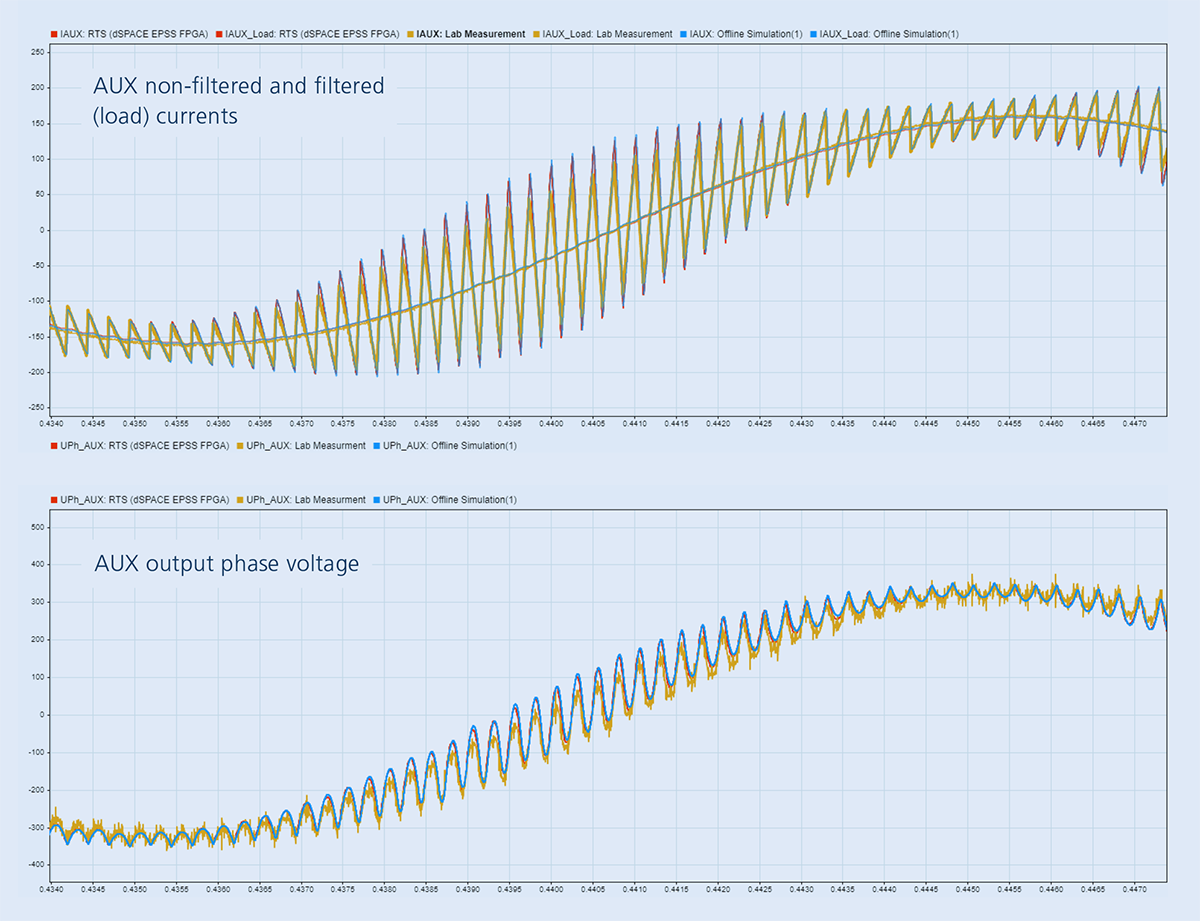
The graphic (Figure 7) shows the results of an open-loop experiment, where the auxiliary DC link is fixed at 750 V, and the auxiliary converter is pulsed with a PWM switching frequency of 4 kHz and a modulation index of m=0.9. The real-time simulation with the EPSS FPGA solution running with a step size of 4 μs is compared with a step size of 0.1 μs offline reference simulation using Simscape Electrical™ (Specialized Power Systems), and with the laboratory measurements. The real-time simulation EPSS FPGA simulation is very accurate – it is almost identical to a much more computationally expensive offline simulation and very closely matches the laboratory results. The difference in simulation compared to the laboratory data results from the ideal nature of the simulated electrical components (i.e., linear Rs, Ls, Cs, etc.). These elements are non-linear in reality, and effects such as resistance temperature dependency and non-linear L-current characteristics are omitted in simulation.
Right to the Smallest Detail – Visualizing the Results
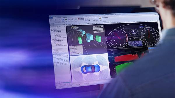
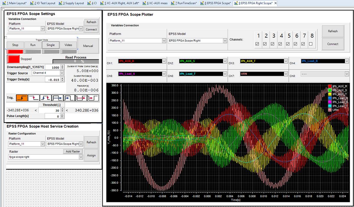
During real-time simulation, the resulting signals are usually monitored on the processor, e.g., using the dSPACE ControlDesk software. However, as the simulation of auxiliary systems on an FPGA is carried out with a precision which cannot be represented on the processor, the processor shows averaged results. The FPGA scope supplied with EPSS, however, makes it possible to accurately record the simulation results in a specific time frame, and to display them conveniently using a ControlDesk extension. Thus, currents and voltages of the power electronics components or the PWM switching signals can be closely observed. Figure 6, for instance, shows how you can use the FPGA scope to set the trigger to capture the relevant signals at an auxiliary load step change from 10% to 100%.
No Burden with the Loads
A further challenge is that the load parameters must be changed during run time. This is not trivial in topology-based simulations, as changed parameters change the discretized differential equations. EPSS provides a graphical user interface for defining Scenarios, i.e., parameter sets for the components included in the circuitry. One can switch between these scenarios in ControlDesk during run time with only a few clicks, and the effect of auxiliary load changes can be easily tested this way.
The Evidence – Laboratory Results
In the end, the ultimate question in every form of simulation is: “How close does the simulation get to the real values?” Hence, parallel to the development of the test environment, ABB carried out corresponding measurements in the laboratory, which confirm that the simulation is very accurate (Figure 7).
Summary and Outlook
Having dSPACE “onboard” means simultaneously ensuring speed, safety, and comfort for public transport. With the dSPACE Development Solution, ABB Traction performs realistic real-time HIL simulations for complete drive chain systems, which have now been extended to auxiliary converters. Encouraged by the excellent results achieved with the EPSS package for auxiliary simulation, ABB Traction will continue to develop the HIL simulator to include even more complex setups in the simulation scope.
dSPACE MAGAZINE, PUBLISHED MARCH 2023

About the author:
Dr. Roxana Ionutiu is Principal Engineer for Real-Time Simulation at ABB’s Traction Division in Turgi, Switzerland.
"Additional thanks to ABB colleagues Thomas Steiner, Dr. Sergio Fraga, Benjamin Grichting, Dr. Gina Steinke, and Thomas Maier for their contribution in several development stages of the AUX RTS, and David Brügger for setting up measurements on the real Auxiliary system in the lab."
Dr. Roxana Ionutiu
About ABB:
ABB is a technology leader in electrification and automation, paving the way to a more sustainable and resource-efficient future. The company’s solutions connect engineering know-how and software to optimize how things are manufactured, moved, powered, and operated. For many years, ABB has also been committed to the development of leading tools for real-time simulation (RTS) to test its products. The dSPACE RTS in ABB’s Traction Division offers an environment for efficient, cost-effective testing of control software of high-performance power electronics systems for rail vehicles and heavy-duty electric vehicles, such as trolleybuses, buses, and trucks.

